home-wrecker.com
New Clipper
by Gary Burchett
The Dan Armstrong Blue Clipper was first marketed in the 1970s as part of the "color" named small effect boxes built by Mu-Tron in New Jersey. Sibling effects were the Green Ringer, Purple Peaker, Red Ranger, etc. These effects were built to plug straight into the guitar or amp. Boxes were simple extruded aluminum square tubing fitted with cover plates. A hard wired male 1/4" plug, toggle bypass switch and female 1/4" out jack were the main features on the boxes.
It has been said the Blue Clipper was the precursor to the MXR Distortion +. Looking at the schematics, they are indeed very similar. The most striking difference is the biasing network on the non-inverting input of the opamp. As it is drawn, the input is intentionally mis-biased to much higher than the typical 4.5V from a 9V supply. As was discussed on Aron's Stompbox Forum, this will chop off much of the positive swing of the waveform. Biasing like this will cause a very characteristic sound by itself. The diode clippers later in the circuit will further alter the waveform. Interest piqued, it was time for some breadboarding.
The original circuit according to the revised schematic posted on Aron's site last December exhibits some strange behavior. The accompanying sound sample (mp3, 122kb) will give you an idea of the strange and dark sound of the unit. The sound is pleasing to the ears, but the output is very low. Using a digital volume meter on my recorder, the output at maximum was around -40dB. This is less than unity for the test signal chain that was used. In the use of fuzzboxes, this is unacceptable. All part values were verified a second time, but the results were the same. Also to be noted was the strange, low-pitched oscillations that came from the box when no signal was input. Stepping out on a limb, I'll say the revised schematic is still wrong.
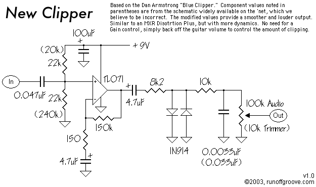
Here is a schematic for one possibility of what the Blue Clipper may really be.
First point of interest is the biasing network. Making these resistors equal will give a much more stable sound. Gone are the oscillations. Output power jumped way up. It is now slightly higher than unity gain. The signal will clean up nicely by using the guitar volume pot. There is no need for a gain pot, unless you use certain effects between the guitar and the Blue Clipper. You can have some fun by trying different values for the resistor connected to ground. Try smaller and smaller values until you reach the value of the upper resistor. As you get smaller, the effects listed above will become more apparent. Try 150k, 100k, 47k, and finally 22k. 100k gives the best balance between the two sounds.
Second point of modification involves changing the Volume pot to 100k. This is a popular mod on MXR units. Output volume came up a few more dB.
The final modification is decreasing the value of the low-pass cap on the output. This brightens the sound a little, but still keeps it from being harsh. This, like the other mods is purely subjective. Choose values using your ears, not meters and scopes.
Lessons learned here: Tinkering with the bias of an opamp is much the same as biasing a transistor. If the bias is too high or too low, you will hear gating and experience strange behavior from the circuit. Clipping will happen in the gain stage. Sometimes this clipping may sound good, sometimes it will take too much away from the circuit.
One could wire a 100k trimmer pot on the input of the opamp to replace the biasing resistors. Lug three will go to +9V, wiper will go to the non-inverting input and lug one will go to ground. Set the pot in the middle of its rotation. Play through the circuit and adjust the trimmer slowly. Try lower and higher until the signal cuts off. Find a setting that sounds good and use it. If you later decide on a different sound, get out the screwdriver and adjust this trimmer.
Possible mod:
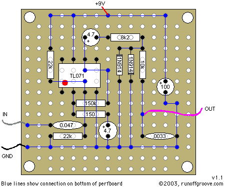
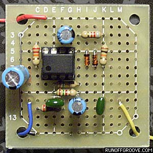
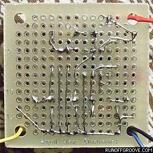
Here is a perfboard layout, designed by Gary, for the New Clipper.
Paul Marossy kindly contributed a PCB layout (PDF, 149K) for the New Clipper.