home-wrecker.com
Uglyface notes
build report by Gary Burchett
After some motivation from Brian, I've built Tim's Uglyface. Since I was interested in the sounds of the original unit with envelope control, it had been on my "to-do" list for some time. The newest version using the 386 chip makes building easier than using the earlier transistor-based envelope control. Since I live in Indiana, it takes a few days to get in an order from Small Bear. I couldn't wait to get cracking on this circuit, so I did some homework to see if I could engineer the missing parts from my small inventory.
The main component that I needed was the vactrol. Brian used the VTL5C3 unit. I searched for the datasheet on the VTL5C3 and found that the stats were 1k resistance when the LED was fully lit. The full dark spec was 10M. I dug through a pack of Radio Shack LDRs and found a unit that was close to the same specifications. I looked for a unit that could get close to 10M with my thumb over the lens of the LDR. My meter showed a resistance of about 1M. I knew the reading would be lower when it was better sealed from light.
For the LED half of the vactrol, I chose a jumbo super bright red LED from Radio Shack. Maximum luminosity was 5000mcd. This is a large LED, about 1/4" in diameter. This was chosen so it would be as close as possible to the diameter of the LDR. This way, I would be able to get the maximum amount of light into the LDR and to make connecting the two easier. I used a small piece of black heat-shrink tubing slightly larger than the LED in diameter. I carefully slid the LED into the tubing slightly more than flush. I used a cigarette lighter to slowly shrink the tubing to hold the LED in place. When the tubing was just tight enough to hold the LED, I slid in the LDR until it bottomed out against the LED. I took particular care to make sure the LED and LDR were straight and with the leads in line. I checked to make sure there was enough tubing to cover the LDR, with a little of the tubing sticking out past the back of the LDR. I carefully applied heat until the LDR was secure. Again, I made sure the LED/LDR were butted together and straight with the leads in line. When this was done, I applied heat a little at a time over the entire assembly. When I felt the tubing was tight enough, I let it cool and harden. I tested the LED and LDR to make sure no damage was caused during the heating and assembly process. After verifying the funtion of both components, I used a tiny drop of super glue to help seal the edges of the tubing to the LED and LDR ends. After this had hardened, I applied a couple of tiny drops of flat black paint to the open ends of the tubing. This coated the backs of the LED and LDR to help reduce light leakage. I let this dry and applied another light coat, being careful not to let any trickle into the assembly to block the LED/LDR. After this paint had dried, I checked the LDR for maximum resistance. The reading came in at 10M. The tubing and glue/paint had blocked most, if not all the light leakage. This fit into the spec of the VTL5C3. With a working vactrol, it was time for installation into the circuit.
Everything was wired per the larger layout found below. There is plenty of space to work if you have some experience with perfboarding. I installed the homemade vactrol vertically with the LED end down to save space. I bent the leads of the LDR over at 180 degrees and attached all 4 leads to the proper places in the circuit. I installed Radio Shack LM386 and TLC555 CMOS chips. The pot wires were twisted together in triplets for each pot to keep the "rat's nest" factor down. This organized the board considerably. With the circuit finished, it was time for testing. I now have a working Uglyface. It just SOUNDS like it is broken!
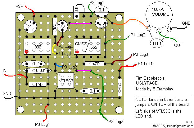
the layout
Gary Burchett was kind (and talented enough) to contribute a perfboard layout for the Uglyface. The layout uses the small Small Bear Electronics or RadioShack size perfboard.
I built the circuit, following Gary's layout, and it works great. A few components are tightly packed, and I would hesitate to recommend the layout to a beginner. After discussing it with Gary, I decided to adapt the layout to the medium sized perfboard. I enlarged the layout to better accomodate the capacitors and vactrol, and to generally loosen up the component spacing.
the mods
I have found that, like octave effects, playing with the guitar tone at minimum and using the neck pickup results in better tracking by the Uglyface.
I added .001 caps to ground at the input and output to further help the tracking and reduce the ear-piercing high end frequencies, respectively. If sonic chaos is your bag, then leave them out. Without them, there will generally be some extra sizzle to the sound.
I also used a 250k frequency pot rather than the stock 100k. This spreads the frequency range out, which is helpful, and allows a lower "low" frequency.


Photos of my perfboard, based on Gary's layout. I did deviate in some places to accomodate component sizes.
