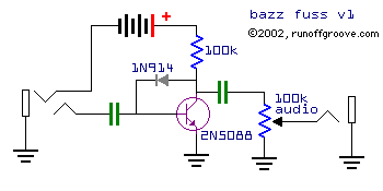
The original schematic specified a 2N3904 transistor, but I like the 2N5088 for better note decay.
The input cap I was 4.7uF, the output .1uF (socketed).
home-wrecker.com
Bazz Fuss
Some time ago, either on the discussion boards or while browsing the 'net, I found myself face-to-face with an ultra-simple circuit named Bazz Fuss. Designed by Christian (né Hemmo), I immediately printed the schematic and built it.
Despite being intended for use with a bass guitar, when I plugged in my guitar the result was a beautiful fuzz with synth-like background textures. The incredible simplicity overwhelmed me. For someone who had been slowly growing restless with each fuzz I built, the Bazz Fuss was some kind of renaissance.
When building it, I made one modification to the original schematic. The original used a 100k gain pot at the front of the circuit, which I relocated to the end of the circuit for use as a volume control. I did this with the thought that I could always use my guitar volume as the gain control, but it really sounds best at full gain.
The original schematic specified a 2N3904 transistor, but I like the 2N5088 for better note decay.
The input cap I was 4.7uF, the output .1uF (socketed).

NOTE: The above perfboard layout, while drawn for the Bazz Fuss v1, can be easily adapted for use with the v2 or v3 simply by using sockets for the capacitors, transistor, and diode.
About a month passed after building the Bazz Fuss, and I was using it as my main fuzz during that time. Then, I saw that Christian had updated the circuit to use a darlington transistor and a smaller resistor. I built this revision at once and while it was slightly more defined, the original sound was still there.
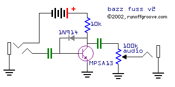
I believe the transistor can be any NPN darlington or even a homemade darlington.
The input cap I used was 4.7uF, the output .22uF. Both caps are socketed.
homemade darlington
More time passed, and I used the Bazz Fusses quite often. Then, after spending a lot of time experimenting with clipping diodes in a different circuit, I realized that I had never tried anything other than a 1n914 as the diode in the Bazz Fuss. I quickly built a third version with nearly everything socketed and began testing.
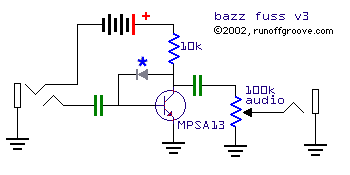
*Diode can be any from chart below, input cap was .056uF, output was .047uF.
The chart below shows my diode experiment findings. I'm using the obnoxiously arbitrary standard of "degrees of dirt" being (from most to least) fuzz -- distortion -- overdrive.
diode(s) |
measured voltage |
notes |
|---|---|---|
| 1N34A | .220v | decent, but output is too low |
| 1N914 | .570v | stock version, great fuzz |
| 1N34A, 1N914 | .780v | a bit more defined, a bit louder |
| (2) 1N34A, 1N914 | 1.0v | almost a hybrid fuzz/distortion |
| orange LED | 1.8v | a hybrid distortion/overdrive |
 Bazz Fuss v3 |
As with many circuits, the input capacitor value has a large effect on the sound. I've tried everything between 4.7uF and .0047uF, and for my tastes, as the diode voltage increases the cap value should decrease. With the LED or the (2) 1n34a, (1) 1N914 combo as the diode, I like the brighter sound of a .047uF. The original really sounds great with the low end menace of a 4.7uF input cap.
My suggestion for building your version of the Bazz Fuss is pretty simple. Follow the Bazz Fuss v3 schematic (above) and socket everything except the 10k collector resistor (visit Small Bear Electronics for the sockets and other great items). That way, you can have as many fun options as I did while experimenting with the circuit. Although I specify an MPSA13 or other darlington, you can use a 2N5088 or 2N5089 (just be sure to use the correct collector resistor value) and still get some interesting sounds. With non-darlington transistors and the 1N914 diode, the sound (to my ears) has more of a synth feel and the note decay is quicker. Tim Escobedo has documented some interesting mods for the Bazz Fuss and you should visit his Bazz Fuss page for the mods and a sound clip. I have recorded a couple clips of the original Bass Fuzz (v1 on this page) as well as the Bazz Fuss v3 (with the LED, picture at right) and they can be found on my Sound Clips page.
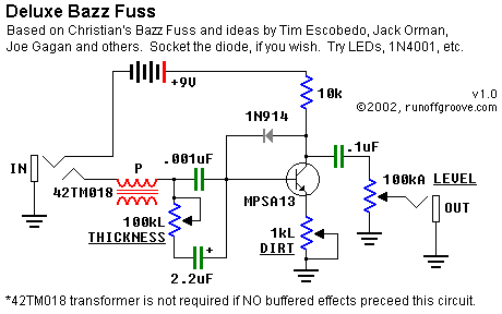
Deluxe Bazz Fuss
by Gary Burchett
The diode can be swapped to your taste, but I've found that other diode sounds (LED or Ge+Si in series) can be emulated with different Thickness settings, and have used a silicon 1N914. With the print values, you should be able to get a good treble boost all the way to a big, fat sound.
All three cap values should be adjusted to taste.
The 42TM018 transformer (Mouser part number) may be eliminated if you are plugging in a passive-pickup guitar directly. The transformer idea is nicked from Tim Escobedo, who got the idea from Jack Orman's article on Pickup Simulation, and Tim says it will preserve the Bazz Fuss' unique tone.
This collection of mods should give you a versatile, simple to build and good sounding OD/Distortion/Fuzz box.
Listen to the Deluxe Bazz Fuss!
Another application of the Bazz Fuss design is the Buzz Box, also designed by Christian. The circuit is simply two BF in series, but the second BF stage uses a germanium diode rather than the usual silicon. The circuit produces a nasty (in a good way), explosive octave-up fuzz similar to the Scrambler and Green Ringer.

